DIY project: How to build a pigtail rack
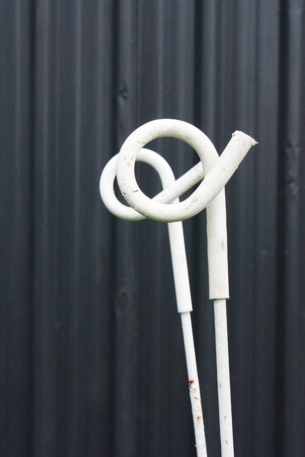
If you’ve got a big, messy pile of tangled pigtails, here’s a simple solution you can build to keep them neat and tidy.
Words and Photos: Bob Browning
Electric fence standards, or pigtails as most of us call them, are an essential and much used item on most farms, big or small. But as useful as they are, their shape ensures they inevitably become entangled when stored or handled in a bundle, resulting in a frustrating mess to sort out before you can use them.
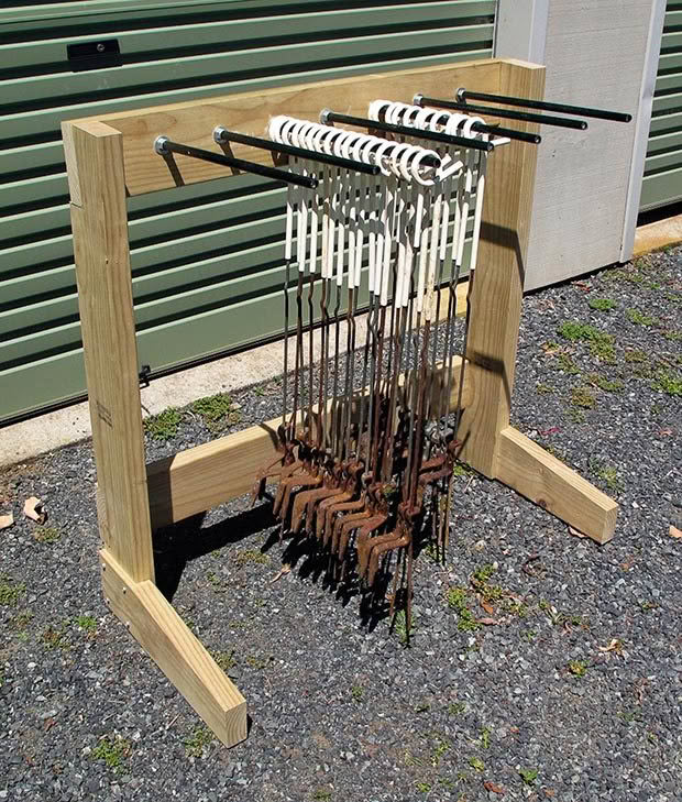
To reduce this problem, I made a rack that stores pigtails tidily and ensures they do not become tangled together during storage. It consists of a timber frame supporting cantilevered steel rods on which the pigtails hang.
This rack holds 112 pigtails comfortably. The height is 1050mm, the length of the frame (excluding the feet) is 1050mm, and the feet are 500mm long. There are seven rods spaced 120mm apart. The length of the rack, and hence the number of rods, could be changed to hold fewer or more pigtails depending on what suits your storage requirements.
TERMINOLOGY
1 The vertical members are sides.
2 The horizontal members which attach to the bottom of the sides are feet.
3 The bottom horizontal transverse member is the bottom rail.
4 The top horizontal transverse member is the top rail.
TIMBER
The timber used in this example is dressed 140 x 45mm Pinus radiata. The actual dimensions of the timber may vary from the nominal dimensions, and at critical areas such as joints I measured the actual timber size and used this in setting out the joint.
STEP 1
The first step is to cut the wood to length, but some decisions need to be made before doing so.
Firstly, a check should be made that the height is adequate for the pigtails it will hold. Some types of pigtail are longer than others bearing in mind that the rods are located 60mm down from the top of the rack.
If the length of the rack is to be changed, the length of the top and bottom rails should be modified in increments of 120mm, the centre to centre spacing of the rods.
The timber lengths used for my rack were:
- sides 1050mmn
- top and bottom rails 1050mmn
- feet 500mm
STEP 2
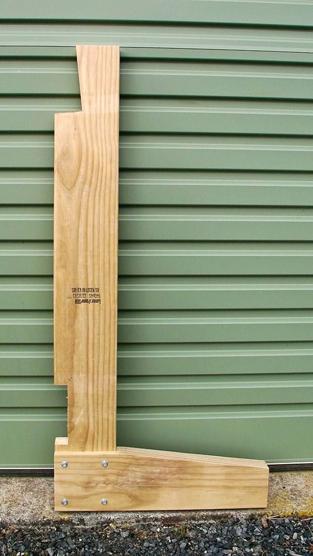
Cut-out at top of sides
The top rail is angled at 6 degrees to the vertical which slopes the rods upwards to stop the pigtails sliding off. The simplest way to set out the required cut-out in the sides for the top rail is as follows.
- Make a mark on the corner between the rear edge and the face of the side, 5mm from the top.
- Make a second mark a further 139mm down, ie 144mm from the top. Use a try square to draw a line at right angles to the edge from the second mark. On this line, measure in 15mm from the edge and make a third mark.
- Draw a line from the third mark to the point where the first mark touches the edge. This line is the back of the top rail. Place the end of the top rail with its back face on this line so that the top corner is flush with the top of the side. Draw a line around it. Extend the bottom edge line back to the edge of the side. The two outer lines form the edge of the cut-out.
STEP 3
Cut-out for bottom rail
I set the bottom rail in cut-outs 30mm deep x 140 mm high in the rear edge of the sides, which left it 15mm proud. The bottom edge is 15mm above the top of the feet. It was fixed in position with two screws each end, 22.5mm in from the end, and 25mm in from the top and bottom edges.
STEP 4
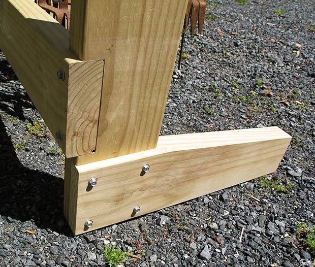
Foot to side connection
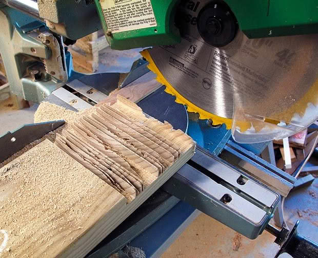
The foot is connected to the side with a modified halving joint, with the foot on the outside. Instead of rebating each piece to half the timber thickness, as for a proper halving joint, I made the rebates 16mm deep, giving a combined finished thickness at the joint of 58mm. Screws were used to fix the joint. You can see another angle in the image below and below right (Step 7).
I cut the four rebates on my sliding compound mitre saw, set to cut 16mm deep, by making repetitive cuts close to or touching each other, and cleaned up the surface with a chisel. The same thing can be done with an ordinary power saw set to the required cutting depth.
STEP 5
Shaping the feet
For aesthetic reasons I tapered each foot, starting at the rebate and tapering it down to a height of 95mm at the toe.
STEP 6
Holes for rods
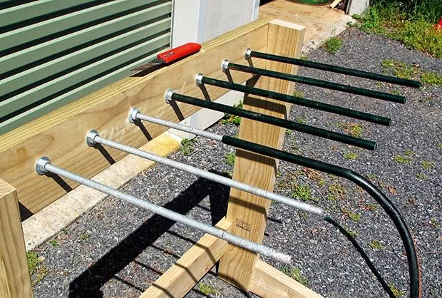
The rods I used were galvanized threaded rod, nominally 12mm diameter, but with an actual measured diameter of 11.7mm. Their length was 1m, which I cut in half to give 2 x 500mm lengths. They are available from building supplies stores, either galvanized or zinc plated.
I positioned the line of holes for the rods 60mm down from the top of the top rail. The end holes are located 165mm in from the ends of the top rail and the holes between spaced 120mm apart, centre to centre.
To make the rods a tight fit in the hole I drilled the holes 11.5mm diameter, a little less than the rod. The holes were drilled with a drill press to ensure they were square to the face of the top rail.
To complete preparation of the top rail I drilled pilot holes for the screws 22.5mm in from the ends. I used two screws at the bottom near each end, spaced 22.5mm apart vertically, with the bottom screw 22.5mm from the bottom edge.
Because the top rail slopes back, the top screws need to be positioned sufficiently low that they do not penetrate the top of the sides. I placed these 30mm from the top of the rail.
STEP 7
Assembly
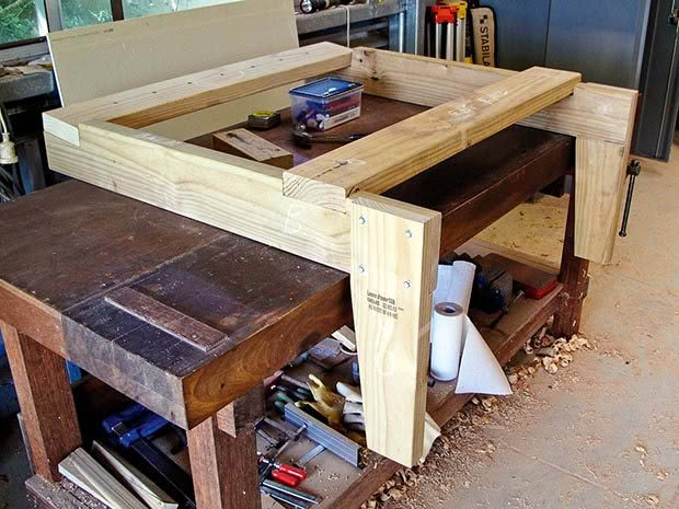
I first attached the feet to the sides, then laid the side assemblies on the edge on my workbench, positioned the correct distance apart.
The bottom rail was screwed into place after ensuring the sides were square to it. The top rail was then screwed into position.
The rods were a deliberate tight fit in the holes, and were wound through the top rail by holding one end of the rod in the chuck of my electric drill. They were secured in place by placing a washer and nut on each side of the top rail.
A length of garden hose was placed over each rod to protect the plastic coating on the pigtails from damage by the sharp thread on the rods, which would lead to shorting out of the electric fence.
FASTENERS
- All fasteners are roofing screws for timber framing with the rubber washer removed, 75mm to connect the top and bottom rails to the sides, and 50mm for the foot to side joint.
- All outer members at the joints were drilled with pilot holes about 80% of the diameter of the unthreaded shank of the screw.
- Roofing screws have a hexagonal head which requires a specialist driver bit, and are driven with a drill/driver or impact driver.
Love this story? Subscribe now!
 This article first appeared in NZ Lifestyle Block Magazine.
